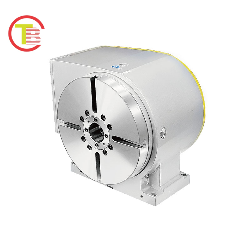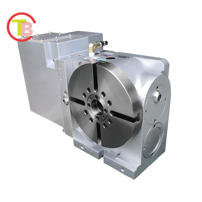
| Item | Data |
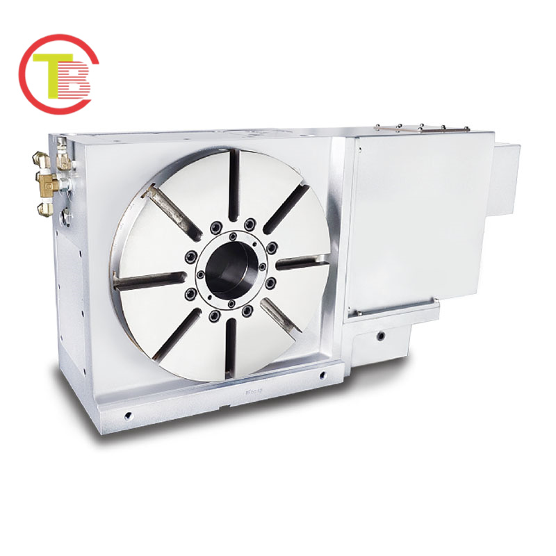
| Application | Vertical or Horizontal |
| Installation Mode | Add-on |
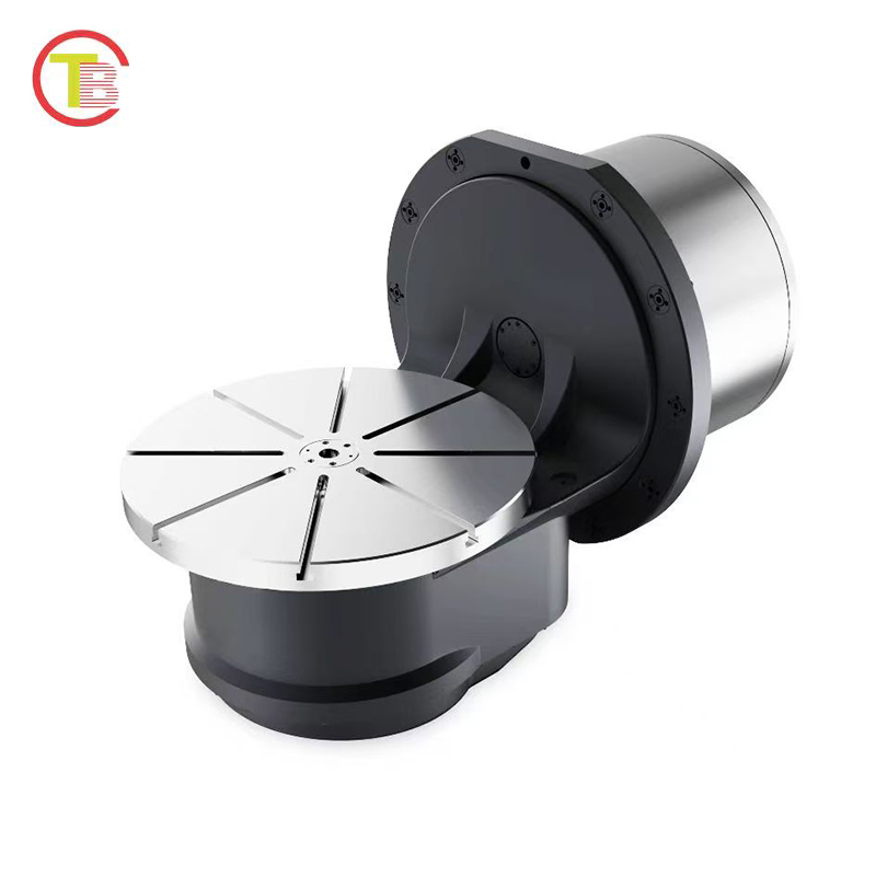
| Table diameter(mm) | ∅210 |
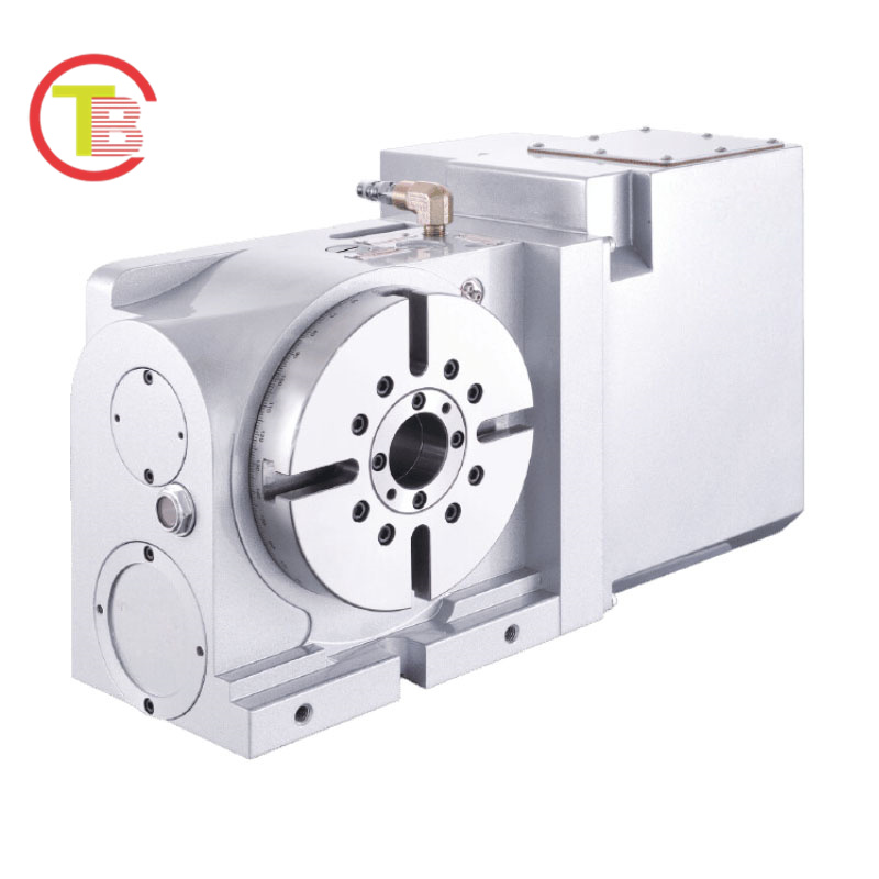
| Inner diameter of mandrel sleeve(mm) | ∅40H7 |
| Diameter of center through hole(mm) | ∅40 |
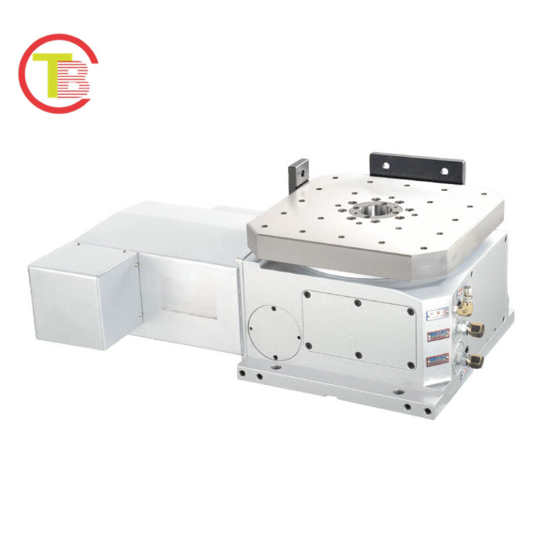
| Center height (Vertical)(mm) | 180 |
| Table height (Horizontal)(mm) | 162 |
| Table T-slot width(mm) | 12H7 |
| Guide block width(mm) | 18H7 |
| Transmission Mechanisms | Roller Cam |
| Min. increment(deg.) | 0.001 |
| Indexing precision(sec.) | 30 |
| Repeatability(sec.) | 6 |
| Clamping system | Hydraulic (3.5 / 35) |
| Clamping torque(N·m / kgf·m) | 48 / 50 |
| Servo motor model(FANUC) (Straight shaft without key) | αiF3 / βiF4 |
| Servo motor model(MITSUBISHI) | HG – S4 / J4 |
| Speed reduction ratio | 130 |
| Max. rotation rate of table(min⁻¹) | 83.3 |
| Allowable inertia load capacity (vertical)(kg·m²) | 0.63 |
| Allowable workpiece load (Vertical)(kg) | 75 |
| Allowable workpiece load (with support table)(kg) | 150 |
| Allowable workpiece load (Horizontal)(kg) | 150 |
| Allowable thrust load (with rotary table clamping) F (N / kgf) | 14225 / 1450 |
| (Axial) *1 Allowable thrust load (with rotary table clamping) Fx (N·m / kgf·m) | 1079 / 110 |
| (Radial) *2 Allowable thrust load (with rotary table clamping) Fr (N·m / kgf·m) | 304 / 31 |
| Driving torque(N·m / kgf·m) | 363 / 37 |
| Net weight (servo motor excluded)(kg) | 52 |
| *1 | If a mechanical brake is not used, this value will correspond to the motor’s holding torque. |
| *2 | The structural limit value, while the actual operating speed will vary depending on the motor. |
| *3 | Roller gear cam or D.D. rotary tables may lose position after power loss or alarm, causing axis shift at restart. Use a brake motor (cover size may vary). |
- Description